You flip the hallway switch, but the light stays dead. Faulty 3 way switch wiring causes flickering fixtures, tripped breakers, and genuine shock hazards that endanger your family every night. This guide walks you through every connection, wire color, and terminal so you complete the installation safely and correctly on your first attempt.
What Is 3 Way Switch Wiring and How Does It Work?
A standard single-pole switch controls a light from one location only. 3 way switch wiring lets you turn the same light on and off from two separate spots, such as the top and bottom of a staircase or both ends of a long hallway.
The system uses two specially designed switches connected by a pair of traveler wires. A hot wire from your breaker panel feeds power into the first switch, and the travelers carry that current across to the second switch, which then routes it to the light fixture.
Each switch carries three screw terminals: one common terminal (dark-colored) and two traveler terminals (brass-colored). Flipping either switch changes the electrical path, so the light responds to both locations independently.
How to Read a 3 Way Switch Wiring Diagram
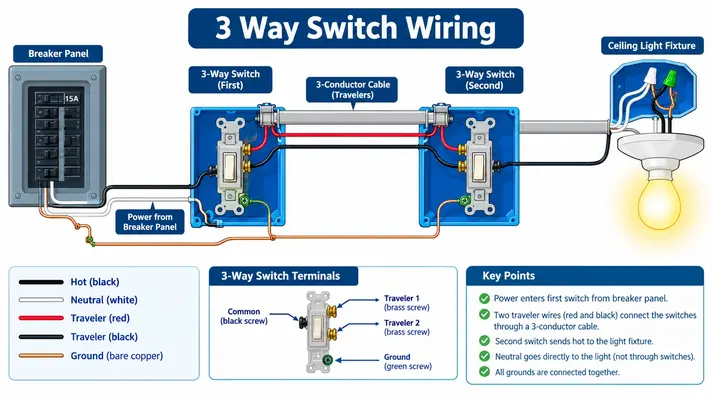
Every 3 way switch wiring diagram follows the same basic layout. Power enters from the left, passes through two switches in the middle, and reaches the light fixture on the right.
Here is the standard circuit path for the most common configuration, where power enters at Switch 1 and the light sits beyond Switch 2:
Power Source (Breaker Panel)
↓ Black (Hot) + White (Neutral)
Switch Box 1
→ Common screw: Black hot wire from panel
→ Brass screws: Red and black traveler wires
→ 14/3 cable runs to Switch Box 2
Switch Box 2
→ Brass screws: Red and black traveler wires from Switch 1
→ Common screw: Black switched-hot wire to light fixture
→ White neutral wire passes through to fixture
Light Fixture
→ Black wire connects to switched hot
→ White wire connects to neutral bundle
Note: Embed a full-color schematic diagram here in your CMS showing the line, traveler, load, and neutral paths with labeled wire colors. A visual diagram dramatically reduces installation errors and keeps readers on the page longer.
The neutral wire (white) never connects to any switch terminal. It passes straight through both switch boxes and terminates at the light fixture. This detail causes more DIY mistakes than any other part of the job.
Tools and Materials You Need Before Starting
Gather everything before you open a single junction box. Running to the hardware store mid-project with exposed wires is a recipe for mistakes.
- Two UL-listed 3-way switches (15-amp or 20-amp, matching your circuit)
- 14/3 NM-B cable for 15-amp circuits or 12/3 NM-B for 20-amp circuits
- Non-contact voltage tester (calibrated and battery-checked)
- Wire strippers and needle-nose pliers
- Phillips and flathead screwdrivers
- Assorted wire nuts (yellow and red sizes work best for 14-gauge)
- Electrical tape (black and colored for re-identification)
- Multimeter with continuity setting for testing
Match your wire gauge to your breaker size. A 15-amp breaker protects 14-gauge wire, and a 20-amp breaker protects 12-gauge wire. Mixing gauges creates a fire hazard.
How to Wire a 3 Way Switch Step by Step
This sequence follows the most common residential configuration: power enters at Switch Box 1, a 14/3 cable connects the two switch boxes, and the light fixture connects at Switch Box 2.
Step 1: Disconnect Power and Verify Zero Voltage
Shut off the dedicated breaker at your main service panel. Place a piece of tape over the breaker so nobody accidentally flips it back on while you work.
Test every conductor inside both switch boxes with a calibrated non-contact voltage tester. Confirm zero voltage on the hot, traveler, and neutral wires before you loosen a single terminal screw. This step is non-negotiable.
Step 2: Identify and Label All Conductors
Separate the wires in each box and identify the line feed (constant hot from the panel), the neutral (white wire bundle), the equipment ground (bare copper), and the traveler conductors.
Use colored electrical tape to tag the common wire at both switch locations. Clear labeling prevents the most frequent 3 way switch wiring mistake: swapping the common and traveler terminals.
Step 3: Terminate Switch 1 (Line Side)
Secure the incoming black hot wire from the breaker panel to the dark common screw on the first switch. Fasten the red and black traveler wires from the 14/3 cable to the two brass traveler screws.
Connect the bare copper ground wire to the green grounding screw on the switch. If the box is metal, pigtail the ground to the box as well using a grounding clip or screw.
Step 4: Terminate Switch 2 (Load Side)
Fasten the red and black traveler wires arriving from Switch 1 to the two brass screws on the second switch. The order of travelers on the brass screws does not matter — either traveler can go on either brass terminal.
Connect the black switched-hot wire leading to the light fixture to the dark common terminal on Switch 2. Attach the ground wire to the green grounding screw.
Step 5: Splice Neutral and Ground Paths
This is where most DIYers create code violations. The white neutral wires must pass continuously through both switch boxes and connect directly to the light fixture. Cap the neutral bundle with a wire nut in each box — never attach a neutral to a switch terminal.
NEC 404.2(C) requires a grounded neutral conductor present at every switch location, even though the switch itself does not use it. This requirement supports smart switches and timers that need neutral power to operate their internal electronics. Pigtail all equipment ground wires together in each enclosure and bond them to metal boxes.
Step 6: Energize and Functional Test
Tuck all wires neatly into the enclosures, mount both switches, and install the faceplates. Restore power at the breaker panel.
Flip Switch 1 up and down, then flip Switch 2 up and down. The light should toggle on and off from either location regardless of the other switch’s position. If the light only works from one switch, you likely swapped a traveler with the common wire on one of the switches.
Common 3 Way Switch Wiring Mistakes That Cause Fires
Connecting a traveler wire to the common terminal is the single most dangerous error. The common terminal must always receive either the line hot (at Switch 1) or the load wire to the fixture (at Switch 2). A misplaced traveler creates unpredictable switching behavior and can leave hot conductors energized inside the box.
Attaching the neutral wire to a switch terminal creates a direct short circuit the moment you restore power. The neutral must bypass both switches entirely and run straight to the light fixture.
Skipping the ground connection leaves the metal switch plate and box energized during a fault condition. Every ground wire in the box must bond together and connect to the switch, the metal box, and the incoming ground from the cable.
Understanding Wire Colors in Your Switch Box
Standard NM-B cable uses a consistent color code that makes 3 way switch wiring predictable once you learn the pattern. Black wires carry hot or switched-hot current. White wires serve as neutrals. Bare copper wires provide the equipment ground path.
In a 14/3 cable, the red wire acts as the second traveler between the two switches. You will see one black traveler and one red traveler running between Switch 1 and Switch 2.
Watch for re-identified white wires. When a white wire carries hot current instead of neutral — such as a switch loop return — the NEC requires you to wrap black or red electrical tape around both ends to signal that it is no longer a neutral conductor.
3 Way Switch Wiring vs 4 Way Switch Wiring
Three way switch wiring controls a single light from exactly two locations. 4 way switch wiring adds one or more intermediate switches between the two 3-way switches, giving you control from three, four, or more spots.
A 4-way switch has four traveler terminals and no common terminal. The two travelers from the first 3-way switch enter one side of the 4-way switch, and two travelers exit the other side to reach the second 3-way switch. The 4-way switch simply reverses the traveler path internally.
The power source and light fixture still connect only to the two 3-way switches at the ends of the circuit. You can chain as many 4-way switches as you need between them for long corridors or large open-concept rooms.
Safety Rules Every Homeowner Must Follow
Never work on a live circuit under any circumstance. Turn off the breaker, lock or tape the panel, and verify zero voltage with a tester before you strip a single wire. The U.S. Consumer Product Safety Commission reports that faulty electrical wiring causes roughly 51,000 home fires every year (cpsc.gov).
Use only UL-listed switches and cables rated for your circuit amperage. Cheap, uncertified components from unknown online sellers frequently fail internal safety tests and overheat under normal loads.
Wear insulated gloves and safety glasses. Keep your workspace dry and well-lit. OSHA electrical safety standards require GFCI protection when you work in damp locations such as basements, garages, or outdoor areas (osha.gov).
When to Call a Licensed Electrician
⚠️ Knob and Tube Wiring Warning: If your home was built before 1950, you may have knob and tube wiring hidden behind plaster walls. This outdated system uses ungrounded, cloth-insulated conductors run through porcelain knobs and tubes. It lacks the equipment ground and continuous neutral conductors that modern NEC code requires at every switch box (NFPA 70, Article 404). Do not attempt to splice modern 3 way switch wiring into an active knob and tube circuit. Hire a licensed electrician to evaluate and upgrade the circuit before making any modifications.
Call a professional if your home has aluminum branch wiring, a fuse box instead of a breaker panel, or switch boxes that lack adequate cubic-inch capacity for the additional conductors. Overcrowded boxes overheat and violate NEC box-fill calculations.
You should also hire an electrician if you cannot confidently identify the line, load, neutral, and traveler wires in your switch boxes. A service call costs a fraction of what an emergency room visit or a house fire will cost you.
How to Troubleshoot a 3 Way Switch That Stops Working
Start by checking the breaker panel. A tripped breaker or blown fuse cuts power to the entire circuit and mimics a switch failure. Reset the breaker and test again.
Remove the switch covers and inspect every wire connection. Loose traveler wires on the brass terminals cause intermittent operation that appears random and frustrates homeowners. Tighten each terminal screw and tug gently on every wire to confirm a solid grip.
Use a multimeter set to continuity mode to test each switch independently. A properly functioning 3-way switch shows continuity between the common terminal and one traveler in the “up” position, then switches continuity to the other traveler in the “down” position. If you get no continuity in either position, the switch is defective and needs replacement.
Switch Type Comparison Guide
| Feature | Single-Pole Switch | 3 Way Switch | 4 Way Switch |
| Terminals (Excluding Ground) | 2 brass screws | 1 dark common + 2 brass travelers | 4 brass/black traveler screws |
| Locations Controlled | 1 | 2 | 3 or more |
| Cable Type Required | 14/2 or 12/2 NM-B | 14/3 or 12/3 NM-B | 14/3 or 12/3 NM-B |
| Common Terminal Present | No | Yes (dark screw) | No |
| Traveler Wires | None | 2 (black and red) | 4 (pass-through) |
| Typical Residential Use | Bedrooms, bathrooms, closets | Staircases, hallways, large rooms | Long corridors, open-concept spaces |
| Installation Difficulty | Easy | Moderate | Advanced |
| Average Material Cost | $2 to $5 | $5 to $12 | $10 to $20 |
Take Control of Your Home’s Lighting Today
Safe 3 way switch wiring starts with the right knowledge, the right tools, and a deep respect for the electricity running through your walls. Follow every step in this guide, double-check your connections against the diagram, and never skip the voltage test.
Your family deserves reliable lighting they can control from any doorway or stairwell without guessing which switch does what. Grab your wire strippers, shut off that breaker, and finish the job right this weekend.
Share this guide with a neighbor tackling their own wiring project, and leave your questions in the comments so we can help you troubleshoot in real time.
Primary Sources:
- National Fire Protection Association — NFPA 70: National Electrical Code, Article 404 (nfpa.org)
- Occupational Safety and Health Administration — Electrical Safety Standards, 29 CFR 1926 Subpart K (osha.gov)
- U.S. Consumer Product Safety Commission — Electrical Safety in the Home (cpsc.gov)